
Many companies are upgrading their data centers to keep up with data demands, while tasked with lowering expenditures and operating expenses.
As these data centers add more fiber connections, many network designers are choosing a centralized network topology with an optical distribution frame to reduce overall floor space while improving long-term energy and cost savings.
Adopting a two-tier switch architecture
A two-tier or leaf-spine network architecture has become the standard for greenfield data centers. In this architecture, access switches are connected to every interconnection switch, providing a redundant path. Traffic runs east-west, reducing latency between access switches.
This is a very scalable fabric. The leaf-spine architecture has led to an increase in top-of-rack and centralized switching topologies. Both of these topologies result in more fiber in the Main Distribution Area (MDA).
Along with centralized switching, a centralized patching field is installed in the MDA, serving as the main cross-connect patching location for all fiber channels in the data center. It can support cabling from network servers, core switches, the SAN, mainframe, and disk or tape storage.
This approach keeps things centralized to make network management easier. In larger facilities, the centralized patching field keeps moves, adds, and changes (MACs) much more manageable.
As data center infrastructure grows, the management area doesn’t. Workers aren’t required to go to remote areas of a facility to do connection work: they’re able to handle it from the patching field.
Other benefits to using a centralized patching field
- A centralized patching field should replicate the switches or respective equipment devices, port for port. This greatly simplifies maintenance and MACs. Also, there is little need to access the cabinets that house high-dollar assets like switches and routers. This makes these assets more secure and minimizes the risk of damage or downtime.
- A centralized patching field does not have to be centrally located. Since it does not require power or cooling, it can be located away from the active equipment in its own floor space, or isolated in a separate room. This frees up premium floor space in the data center for additional revenue-generating cabinets housing switches and servers.
- Traffic can easily be redirected at the patching field while equipment gets serviced or changed out, saving time and lowering operating expenditures associated with tech refreshes.
Typically, centralized patching fields present as traditional cabinets or an open frame with no active equipment inside. Traditional 19-inch cabinets maintain a consistent look with other cabinets in a data center.
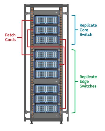
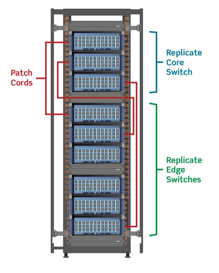
The image to the left represents a centralized patching field in a traditional cabinet, using 4RU enclosures. The top three enclosures replicate core switches, while the middle and bottom enclosures replicate edge switches.
Ninety-six fibers per rack unit is an optimal manageable density, accommodating up to 3,456 fibers in a cabinet.
There are ultra-high-density enclosures available today that can raise that number to more than 5,000 fibers per cabinet.
However, managing cords and trunks in such an ultra-high-density application with traditional rack enclosures can become challenging. There is little room for adequate slack management, and fiber bend radius becomes a concern, especially for trunks entering the cabinet.
Distribution frame solutions are most often used by carriers in central offices, where tens of thousands of fibers are being managed. However, in recent years, data centers have begun adopting the frames. They are capable of patching thousands of fibers, and are designed with cable management to alleviate the challenges of higher densities.

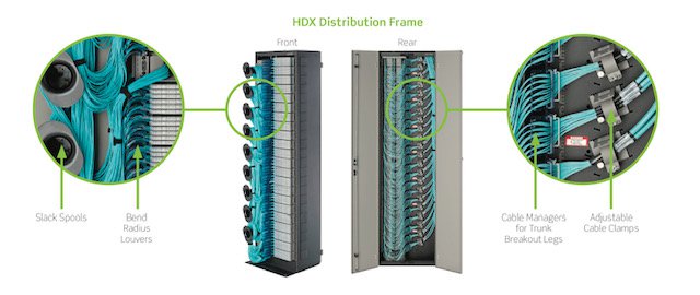
For example, the Leviton HDX Fiber Distribution Frame has the ability to patch 3,168 LC fibers or 15,552 MTP fibers on only one 2' x 2' data center floor tile (for raised floor applications), and includes vertical and horizontal cable managers integrated into the frame.
The fiber density can easily double or triple based on occupying the same floor space as a traditional cabinet. It includes slack spools and cable clamps for properly routing cords and trunks, and unique patch decks with trays that handle horizontal cord management.
In contrast, vertical and horizontal cable management solutions for traditional cabinets are sold separately and installed at the job site. Some cabinet manufacturers kit the cable management with the cabinet, but cable management will need to be moved or adjusted horizontally and vertically based on the layout.
Also, a distribution frame leaves a much smaller footprint than a traditional cabinet, with the ability to occupy only one 2 x 2-foot data center floor tile, while a traditional cabinet occupies up to four data center floor tiles.
Reducing the footprint while adding density opens up space for additional cabinets dedicated to network switches and servers — the revenue-generating cabinets in a data center.
As with traditional cabinets used for cross-connect patching, a distribution frame replicates core switches in the top half and edge switches in the bottom half. When patching within one frame, the distribution frame requires only one length of patch cord. This means data center managers don’t need to stock multiple-length patch cords.