

Network visibility is a top priority for many IT managers. When networks become larger and more complex, monitoring for performance and security is no longer optional, it becomes critical. Financial, medical and telecom markets need visibility tools to manage their networks and handle troubleshooting quickly and efficiently. Just as important, the monitoring needs to be done without adding any disruptions to the network.
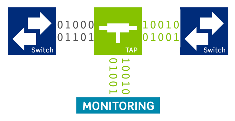
That’s why more IT directors are using passive optical TAPs to monitor network links.
What is a TAP?
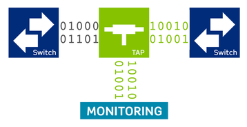
A traffic analysis point (TAP) is designed to allow traffic to be monitored for security or network performance. The tap is positioned in the passive cabling system between a host and recipient device. TAPs create greater visibility into a network. They provide a window into your data for security or surveillance. But they also make it possible to look at data packets and advise the network administrator on how the network is performing in real time.
Analyzing data in real time can be as simple as viewing a bank transaction or seeing if a health care record was placed in the correct file. When there are millions of these transactions happening constantly, TAPs will help find any bottlenecks in your network.
TAP vs SPAN
A Switch Port Analyser (SPAN) is another common way to monitor traffic. It is a software function in a switch that is offered by most network switch manufacturers. A SPAN provides mirror port functionality, duplicating traffic of incoming and outgoing ports. Since it is a software function within the switch, SPANs do not require placing an additional device into the network link.
However, there are limitations when using SPAN ports. First, they can negatively impact the functionality of the network, due to slowing down traffic and creating potential bottlenecks. Also, ports can become oversubscribed so they end up becoming the lowest priority on the network, resulting in dropped packets and less accurate visibility than you require. As a software function within the switch itself, SPAN traffic can be reconfigured daily, which may result in inconsistent reporting.
Passive optical TAPs are much more common in enterprise data centers, as they offer a number of distinct advantages:
- TAPs pass all link traffic for monitoring. Even corrupt data will not be rejected, so users are able to see everything in real time
- Unlike SPAN ports, there is no programming or switch configuring required with a passive TAP
- They are invisible to the network: they place no burden on the network or any changes to packets or data transmitted through the link
- They offer full duplex port monitoring with a transmit and receive path that is scalable at data rates
- This means you won’t encounter oversubscription when using a passive TAP
- TAPs that are built into the existing patching environment reduce the number of connections required in the structured cabling, taking at least two connections out of the link
How a passive TAP works
An optical TAP is essentially a splitter that divides the light into two or more outputs. It can also combine two or more inputs into a single output. For example, in Figure 1 below, the input in Channel 1 (C1) from the host is passed through the TAP to the recipient (P1). The transmit not only pushes through the live traffic to the recipient, it also transmits through the TAP to the monitoring tool (R1).
There are two primary technology options for creating a TAP splitter: a fused biconical taper, or thin film filters, as shown in Figure 2. The fused biconical taper is the older of the two technologies, and while it is easier to produce than thin film filters, it creates a higher insertion loss. The thin film filters - which are made up of a stack of layers of refraction which both reflect and transmit light - is the preferred method. It provides a lower loss that is critical for a TAP solution, since that loss can impact the power budget in the link.
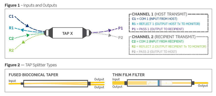
The construction of a splitter makes the flow of data directionally specific. The monitoring outputs (reflect fibers) only receive traffic. In each TAP, one monitoring/reflect output receives transmitted traffic from the original host device and the other receives response transmission from the recipient device.
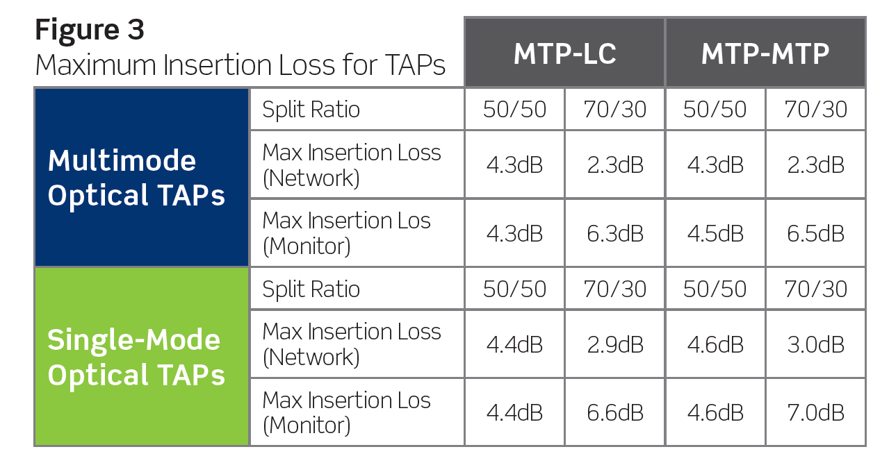
A TAP cassette has multiple tap splitters based on the number of designed outputs. Each signal (per TAP splitter) is split to “live” and “monitoring” output signals at a pre-determined ratio - typically 50/50 or 70/30 (70 live and 30 monitoring).
A 70/30 split ratio is generally the preferred method, as it dedicates a higher percentage for network traffic, avoiding any dropped packets. The 70/30 split is most commonly used in 1 Gb/s and 10 Gb/s networks. However, at higher speeds such as 40 Gb/s and 100 Gb/s, the 50/50 ratio is more commonly used in order to meet power budgets.
Figure 3 lists the maximum insertion loss for TAP cassettes in both 50/50 and 70/30 split ratios. The numbers listed include the loss from the splitter inside, as well as the connections on the rear and front. TAP cassettes on the monitoring side can become much lossier than conventional network cassettes, so it is important to consider low-loss solutions for these connections.

Addressing network speeds and fiber types
When selecting the appropriate model of passive TAP, it is important to know what network speed, wavelength, or link distance you will be using as these factors will affect the power budgets in your network.
Single mode
Typically, single-mode fiber is used in longer distance links, but it is gaining popularity in shorter data center links, as short as 150 meters. These single-mode installations are typically for higher data rates, such as 40 Gb/s and 100 Gb/s. There are single-mode TAP solutions designed specifically for these applications.
Multimode
Most multimode fiber is used for short reach and data center applications, and the transceivers used for multimode are usually short reach or “SR” products that use 850 nm VCSELs, such as QSFP+ 40G-SR4 and SFP+ 10G-SR4. However, newer transceivers on the market can operate at wider spectral ranges, or use multiple wavelengths. These different options will function differently inside a passive optical TAP.
For example, a Cisco 40G BIDI carries both transmit and receive traffic on the same fiber. This requires a special TAP splitter to support this distinctly different technology. One would not be able to use the exact splitter technology shown in Figure 1, as it does not consider dual wavelengths and transmit and receive paths on a single fiber.
Fiber connectors and the passive splitter can both impact the optical power budget available for the link and monitoring equipment. In addition, the fiber type can also impact the budget. While both OM3 and OM4 are the most common data center fibers deployed, OM4 offers higher bandwidth and improved distances. For this reason, Leviton recommends using an OM4 solution when deploying passive TAPs into a network.
Deploying passive TAPs in the network
Traditionally, when installing a passive TAP, one would add a dedicated TAP panel and extend a patch cord from the TAP panel to the network patching environment. In contrast, there is now TAP technology that is built into an existing cassette footprint so it can be part of the patching environment, instead of an additional element added to the network. This integration eliminates the need for a dedicated TAP panel and therefore removes two additional connections from the channel.
The integrated design also conserves rack space, since no additional TAP panel is required. With TAP ports on the rear of the cassette instead of front, no patching density is lost.
Passive optical TAPs have become a popular choice for creating network visibility and enhancing network security. They place no burden on the network, and don’t contribute to dropped packets. Passive TAP adoption will continue to grow, with products now available that can be built into the existing patching environment, reducing the number of connections required in the structured cabling infrastructure, and in turn lowering channel insertion loss.
Eddie McGinley is director of fiber product management at Leviton Network Solutions Europe